Article Information
- Dashjamts Dalai, Batsaikhan Anand, Dugersuren Enkhbaatar. 2015.
- Permafrost and geotechnical investigations in Nalaikh Depression of Mongolia
- Sciences in Cold and Arid Regions, 7(4): 438-455
- http://dx.doi.org/10.3724/SP.J.1226.2015.00438
Article History
- Received: April 13, 2015
- Accepted: June 1, 2015
2. Soil Trade LLC, Ulaanbaatar, Mongolia;
3. Novosibirsk State University of Architecture and Civil Engineering, Novosibirsk, Russia
1 Geology and geocryologic conditions of Nalaikh Depression 1.1 Geographic condition
Geographically, the Nalaikh Depression is located in the central area of Mongolia, 36 km from Ulaanbaatar City. The depression is located southwest of the Khentii mountainous range, a tectonic depression occupying an area of 17km×12km(Figure 1). Geologically, this region comprises metamorphic and sedimentary bedrock with Lower Cretaceous sediment, 10 to 20 m deep. The sediment is covered by neogenic and Quaternary formations which are rich in gravel, s and and clay soils. The first permafrost investigation in Nalaikh Depression was performed by a Russian researcher N. A. Tsytovich(Jukov, 1957) and subsequent studies by Mongolian researchers N. Lonjid, G. Tumurbaatar and Ts. Tsagaan(Lonjid et al., 1969).
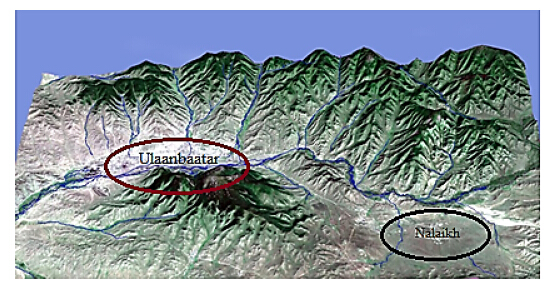 |
| Figure 1 Geologic structure map showing location of Ulaanbaatar City and Nalaikh Town(District of UB City) |
Scattered permafrost detected in the Nalaikh Depression has an average annual temperature of −3.5 °C. Permafrost thickness varies between 15.0 and 55.0 m with temperatures ranging from −0.7 to −1.5 °C. The seasonal freezing depth in lower areas is between 1.5 and 2.0 m and in high elevated areas(sloped to the south)is between 3.4 and 4.5 m. Small crystals and ice veins are encountered in gravel, s and and clay soils at depths between 1.5 and 6.0 m. Permafrost soil moisture content varies from 13.7% to 20.0%.
1.2 Geologic structureThe Nalaikh Depression is underlain by Lower Carboniferous s and stone, metamorphic shale, Lower Cretaceous claystone, conglomerate, coal, clay, and Quaternary clayey depositions. The stratigraphy of the site is defined by the following systems(Myagmarjav, 2012):
· Unclassified Carboniferous system(C1): Lower Carboniferous bedrock formation predominating, siliceous schist and s and stone was encountered in the northern area with thickness of over 3, 000 m.
· Lower Cretaceous system(K1)of Zuunbayan. The formation fills the Nalaikh Depression region and its weathered rock outcrops formed eluvium, diluvium and proluvium depositions. The formation is characterized by Lower Cretaceous claystone, s and stone, coal and poorly grained coarse deposits.
· Lower and Middle Quaternary system(QI-II). The investigation site is characterized by Lower and Middle Quaternary lacustrine and lacustrine-aluvium deposits, insular spreading within river valleys and dried streams, predominating clay, coarse grained deposition including clayey material.
1.3 Tectonic and geologic development of Nalaikh DepressionIt is clearly visible from the formed sediments through the Devonian and Carboniferous periods that the Nalaikh region was a seafloor at the beginning of mid and late-upper Paleozoic. Lacustrine sedimentation was formed by s and y clay and clayey materials carried from the surrounding mainl and and accumulated in the sea bottom. During subsequent periods the area was subject to uplifting, thrusting and folding events of tectonic evolution. The results are presently visible from tectonic thrusts and intrusive massives formed during the Triassic-Jurassic periods. The uplifting continued until the Cretaceous, and during the Triassic-Jurassic periods the area possessed a very dense green forest under a warm and humid climate. During the Cretaceous, the faults were reactivated thus deep lakes formed which accumulated Carboniferous clayey materials of deep forest and bushes. The existence of these lakes in the Lower Cretaceous was short. The evidence for the loose condition of clayey deposition suggested that during the Tertiary or Paleogene-Neogene periods ground re-uplifting had taken place.
It is considered that a shallow small lake existed in the Early Quaternary. This period was characterized with light erosion process, therefore the accumulated sedimentation contained coarse and angular grains. The glacier process was recorded during periods of the Lower and Middle Quaternary, then through the Upper and Modern Quaternary lake bed was covered by clayey deposition and top soil.
1.4 Geomorphologic featuresThe Nalaikh Depression is composed of the following geomorphologic elements:
· Denudation-tectonic evolution of middle highl and area;
· Denudation evolution of rolling topography;
· Denudation-accumulation of hills and knolls.
Bayan-Zurkh Uul(mountain) and its branch mountains are affected by denudation-tectonic processes. The peaks of these medium-height mountains are rounded, and occasionally contain rock outcrops of 1.0-3.0 m high. The mountains are marked by forest and ridges on the northern sides and by physical weathered metamorphic predominating granite fragments on the southern, eastern and western sides.
Denudation and rolling topography is marked in the western boundary of the depression in direction from north to south and in the center. The absolute height of hills varies between 1, 480-1, 590 m with relative height of 30-60 m. Hills and knolls are slightly sloped 2°-4° and some hills are inclined in distance of over 2 km.
Denudation-accumulation process of hilly and knoll area is wide spread in the northern, northeastern and eastern sides of Nalaikh region. Deposition of hilly area is comprised of diluvium-proluvium deposits primarily clay and clayey materials. Small amounts of lacustrine deposition are encountered in the eastern side of the closed Nalaikh Coal Mine, where the new proposed university campus, logistics center, thermoelectrical heating plant and other buildings are planned.
1.5 Climatic parametersClimatic characteristics of the area were obtained from the Climatic and Geophysical Features for Construction Design(CNR-23-01-09)which are presented in Tables 1 and 2(Jambaljav et al., 2008).
| Month | I | II | III | IV | V | VI | VII | VIII | IX | X | XI | XII | Annual |
| Temperature(°С) | −24.1 | −18.2 | −11.6 | −1.3 | 6.8 | 11.8 | 13.9 | 11.9 | 5.3 | −3.0 | −14.4 | −21.6 | −3.7 |
| Seasonal thawing depth(m) | Maximum daily relative humidity | Precipitation | |||||||
| Coarse grained material | Clay | The warmest month | The coldest month | Annual | Warm season | Daily maximum | Observed date | ||
| 3.91 | 2.74 | 56 | 75 | 372.9 | 354.9 | 55.5 | 1994.08.07 | ||
According to distribution of continuous permafrost, the Nalaikh Depression region is located within sparsely insular permafrost that is sporadic and scattered(Figure 2). The region is characterized with relict permafrost, which points that the climatic conditions when it was formed are differ from current conditions.
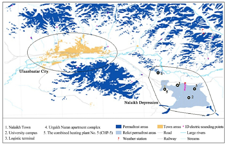 |
| Figure 2 Permafrost distribution map of areas surrounding Ulaanbaatar City |
Nalaikh Town was established as one of Mongolian's major industrial complex in the coal rich Nalaikh Depression. During the 20th Century numerous buildings and facilities were constructed such as administration buildings, shafts, thermoelectrical heating plant, water tank, social and cultural facilities. The heating plant and administrative building are shown in Figure 3.
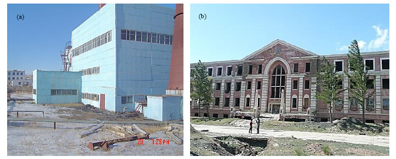 |
| Figure 3 Heating plant(a) and administration building(b)of Nalaikh coal mine constructed with ventilation hollow and insulation techniques |
Construction of buildings in permafrost conditions of Nalaikh was accomplished by specialists from Kuzbas Project Institute of Soviet Union(now Ukraine)following the principle advocated by Russian professor N. A. Tsytovich of keeping the permafrost in place. The buildings were constructed with ventilation hollows on reinforced concrete foundation at a depth of 4 m. An additional cooling system was used during the summer season for the main buildings. For instance, an additional wall was constructed surrounding the mining shaft entrance according to N. G. Trupak's recommendations to provide air circulation so as to keep the structure cool(Jukov, 1957). Thus, the principle of preserving permafrost conditions was successfully implemented in the southern boundary of the Northern Hemisphere permafrost region. But, in the early 1990s, the coal mine was closed as some buildings and construction facilities were damaged from subsidence due to permafrost thawing. The damage is limited only to buildings constructed on permafrost while the other structures built on non-permafrost soils are in good condition.
Due to expansion of Ulaanbaatar, the area of Nalaikh Town previously exploited for coal mining facilities is now planned to be turned into a new settlement. The Combined Heating Plant No. 5(CHP-5), airport, logistic terminal, industrial facilities, factories and university campus are planned to be built. Therefore, engineering geology assessment and geotechnical investigations have been conducted on three sites in the area: university campus, Ulaanbaatar terminal, and Urgakh Naran residential complex.
Preliminary results from these investigations show that different parts of the Nalaikh area have different geocryological conditions. Some sites contained continuous distributed permafrost with thickness reaching up to 50 m while other areas have scattered and sometimes sporadic permafrost of 4-10 m thick at 5.5-7.6 m depth from the surface.
Geotechnical conditions of permafrost in the Nalaikh Depression was studied from 1966 to 1976, and then in 1981 by State National Construction Center. Further detailed studies on permafrost were provided through establishment of the soil monitoring station by the Mongolian Construction Engineering Exploration Institute. The Institute of Geography and Permafrost Research Laboratory of Mongolian Academy of Sciences have carried out long term observations of permafrost conditions via observations points in drilled exploration boreholes. Average ground temperature measurements in these studies between 1996 and 2007 are presented in Figures 4 and 5(Jambaljav et al., 2008).
Figure 4 presents permafrost temperatures from 1996 to 2007 while Figure 5 presents temperature fluctuations at different permafrost depths from 2005 to 2006. It is obvious that underground warming is present and the temperature is increasing. Permafrost is spread unevenly through the Nalaikh Depression and the planned site of university campus in Shiveet Valley is in an area with the highest concentration of permafrost.
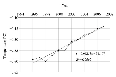 |
| Figure 4 Permafrost temperature fluctuation at depth of 15 m |
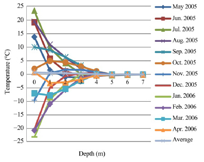 |
| Figure 5 Permafrost temperature curve of Nalaikh Depression from May 2005 to April 2006 |
The proposed university campus site in Shiveet Valley is located in the southeastern part of Nalaikh Town. The site has the following characteristics. First, regarding surface relief, the site is inclined in direction from south to north with relative differences between 1, 460 and 1, 538 m. Rolling topography is located in the north and center of the region, with pingos reaching a height of 3.0 m, which melt forming numerous small ponds, holes and cavities in the surrounding area. Due to seasonal freezing cycle the surface has become hummocky. Second, in regards to underground conditions, the permafrost zone is characterized by Quaternary aged predominating coarse grained deposits including clayey material, and Cretaceous clayey deposition(Myagmarjav, 2012). Permafrost is ice-rich and varies from massive to ataxite cryogenic structure over a wide range of formations. The groundwater dynamics are in the upper and mid layer of permafrost. The upper permafrost layer reaches the seasonal freezing boundary. The permafrost has permanently the temperature of minus Celsius degrees up to 15-m deep. The soil within seasonal freezing depth is subject to extensive heaving.
To determine the geocryological condition for the proposed university campus, 175 boreholes with depths ranging between 6 and 22 m were drilled. Borehole location was based on numerous factors such as surficial and geological features, permafrost distribution, physical and geological processes on the surface. According to relief features, the site can be divided into two parts: firstly, area of single or group of pingos with height of 3-4 m, with dried stream and rock outcrops; secondly, relatively even ground surface with small sized hummocks developed due to seasonal thaw-freezing cycle. The pingos has ice cores and seasonal thawing which results in the top melting and collapsing, resulting in thermokarst hollows, some of which are filled with meltwater from permafrost.
Figures 6, 7, and 8 show site conditions under the influence of thermokarst, physical and geological development, hummocks and pingos, and frozen soil samples taken from the completed borehole which describes the permafrost distribution(Myagmarjav, 2012). The investigated site is situated within a seismic zone of 7 degree of intensity.
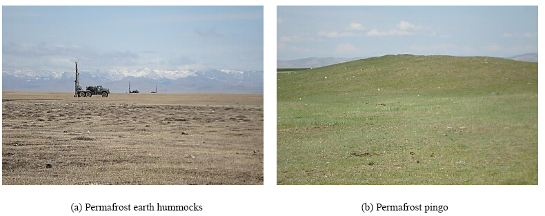 |
| Figure 6 Land scape formation resulting from seasonal freezing |
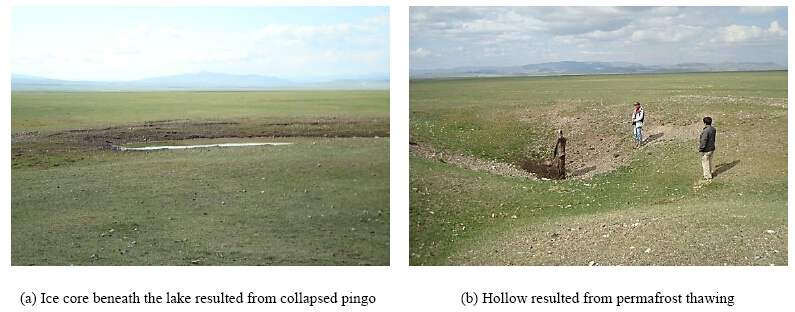 |
| Figure 7 Land scape formation resulting from permafrost thawing |
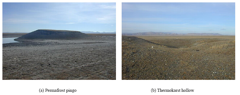 |
| Figure 8 Thermokarst land scape in Shiveet Valley |
The geological survey by borehole drilling, soil sampling along with experiments determining the physical properties of the soil, underground temperature measurements, monitoring and observation of exploration boreholes point to evidence of continuous distribution of permafrost in this area.
The geocryological condition of the selected site is determined by climatic conditions, form of ground surface formation and influence of environmental factors. This data was then compared with data from previous investigations and surveys.
Upon completion of the permafrost study and investigations of the drilling process in Nalaikh region, soil textures are presented in Figures 10 and 11 and summary of permafrost temperatures are presented in Figure 12. Shiveet Valley is underlain by Cretaceous aged massive and ataxite cryogenic structure predominating clayey material and massive texture of gravelly deposition including silty sand and clayey sand soils(Figure 9).
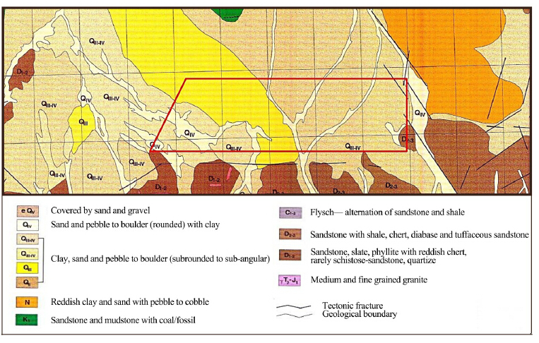 |
| Figure 9 The geological structure of deposition and rock formation at the university campus site |
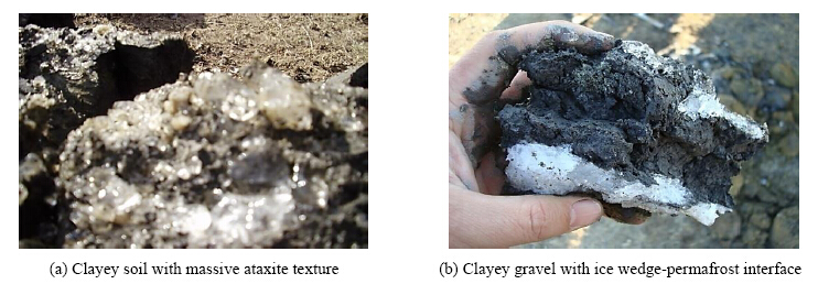 |
| Figure 10 Permafrost soil textures of Shiveet Valley |
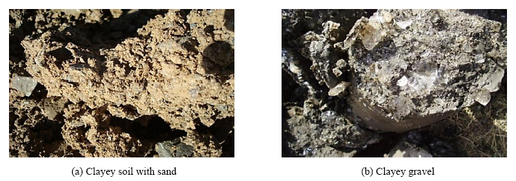 |
| Figure 11 Examples of soil samples |
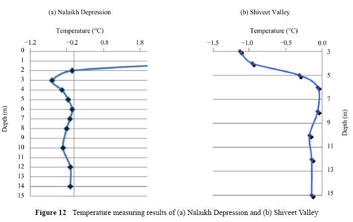 |
| Figure 12 Temperature measuring results of(a)Nalaikh Depression and (b)Shiveet Valley |
Based on observation and investigation, it should be noted that the site for the proposed construction buildings of the university campus is located within significantly challenging geotechnical conditions.
Based on soil origin, age, physical and mechanical characteristics, thermal and technical characteristics, university campus soil is classified into four engineering geological elements(EGE).
· Poorly graded sand with gravel and silt; light yellowish colored; hard consistency(EGE-1)
· Poorly graded gravel with sand and silt; light yellowish, yellowish brown, hard consistency in seasonal freezing zone and massive texture in permafrost zone(EGE-2)
· Clayey gravel with sand , light yellowish, yellowish brown, hard consistency in seasonal freezing zone and massive texture in permafrost zone(EGE-3)
· Lean clay, light grey or dark grey colored, massive, interface and ataxite textured(EGE-4)
Poorly graded gravel with sand and silt along with clayey gravel with sand is detected in both seasonal freezing zone and permafrost zone. Laboratory test results of physical and mechanical properties of the site soil are presented in Tables 3, 4 and 5.
| Physical properties | EGE-1 Poorly graded s and with gravel and silt | EGE-2 Poorly graded gravel with s and and silt gravel | ||||
| Natural moisture content, W(%) | 0.076 | 0.084 | ||||
| Plasticity index, Jp | 0.051 | 0.059 | ||||
| Specific gravity, γo(g/cm3) | 2.69 | 2.69/2.70 | ||||
| Density, γs(g/cm3) | 1.79 | 2.21/1.99 | ||||
| Dry density, γd(g/cm3) | 1.66 | 2.04/1.65 | ||||
| Porosity, n(%) | 38.24 | 24.17 | ||||
| Voids ratio, e | 0.619 | 0.319 | ||||
| Degree of saturation, Sr(%) | 0.33 | 0.70 | ||||
| Soil classification | EGE-1 Poorly graded s and with gravel and silt | EGE-2 Poorly graded gravel with s and and silt | EGE-3 Clayey gravel with s and gravel | EGE-4 Lean clay | ||
| Gravel d >20 mm | -- | 59.2 | 56.1 | 0.3 | ||
| S and d = 0.02-2.0 mm | 0.5 | 26.3 | 24.8 | 37.0 | ||
| Silt d = 0.02-0.005 mm | 72.2 | 79.9 | 10.9 | 36.9 | ||
| Clay d ≤0.005 mm | 27.3 | 6.6 | 8.2 | 25.8 | ||
| Physical properties | EGE-2 Poorly graded gravel with s and and silt | EGE-3 Clayey gravel with s and | EGE-4 Lean clay |
| Total moisture content of frozen soil, Wtot(%) | 0.206 | 0.227 | 0.341 |
| Water-absorbing capacity/hygroscopic moisture content, Ww(%) | 0.083 | 0.090 | 0.175 |
| Water content interface between the ice, Wm(%) | 0.149 | 0.159 | 0.280 |
| Ice water content in the pore spaces between the solid soil particles, Wic(%) | 0.072 | 0.069 | 0.105 |
| Water content in unfrozen soil, Wi(%) | 0.057 | 0.069 | 0.049 |
| Liquid limit, Wl(%) | 0.200 | 0.221 | 0.506 |
| Plastic limit, Wp(%) | 0.139 | 0.136 | 0.260 |
| Plasticity index, Jp | 0.061 | 0.085 | 0.246 |
| Consistency, JL | 1.100 | 1.060 | 0.340 |
| Specific gravity in frozen condition, γs(g/cm3) | 2.700 | 2.690 | 2.740 |
| Specific gravity, γo(g/cm3) | 1.990 | 1.950 | 1.790 |
| Dry density, γd(g/cm3) | 1.650 | 1.590 | 1.340 |
| Voids ratio, e | 0.636 | 0.636 | 1.048 |
| Degree of saturation in the pores, Sr(%) | 0.750 | 0.540 | 0.870 |
| Total ice content, itot(%) | 0.320 | 0.140 | 0.400 |
| Ice content, iic(%) | 0.100 | 0.070 | 0.080 |
Figure 13 shows a geological section of the Shiveet Valley soil which consists of four engineering geological elements(EGE), with only EGE-3 appearing in both seasonal freezing zone and permafrost zone.
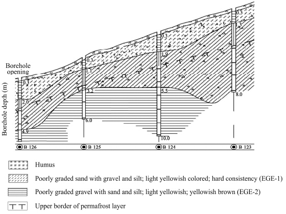 |
| Figure 13 Geological section of Shiveet Valley (borehole numbers 126, 125, 124, 123) |
According to the construction norm, clayey gravel with sand , gravelly soils are determined to have a heaving potential. Degree of heaving for encountered soils in seasonal freezing depth is characterized as follows:
· Poorly graded sand with gravel and clay--slight
· Poorly graded gravel with sand and silt--slight
· Clayey gravel with sand gravel--high
Calculation of mechanical properties for the encountered soils is given in Table 6. Permafrost soil characteristics are given as follows in Table 7.
| No. | Soil name | Cohesion(kPа) | Angle of internal friction(°) | Module of deformation, Е(MPa) | |||
| СI | СII=Сn | φI | φII=φn | ||||
| 1 | Poorly graded s and with gravel and clay | 11 | 16 | 23 | 27 | 20 | |
| 2 | Poorly graded gravel with s and and silt | 11 | 16 | 38 | 44 | 45 | |
| 3 | Clayey gravel with s and | 17 | 26 | 35 | 40 | 39 | |
| Soil name | Physical properties | Ice characteristics | Design strength | Thermo-technical characteristics | ||||||||
| Wtot(%) | γo(g/cm3) | D(g/cm3) | Iс(%) | Lв(%) | А0 | ар1 | ар3 | λ(kCal/(m∙h∙°C)) | C(kCal/(m3∙°C)) | |||
| Poorly graded gravel with s and and silt | 0.206 | 1.99 | 1.65 | 0.32 | 0.10 | 0.04 | 0.05 | 0.068 | λth=1.40, λf=1.50 | C th=670, Cf=510 | ||
| Clayey gravel with s and | 0.227 | 1.95 | 1.59 | 0.37 | 0.13 | 0.05 | 0.07 | 0.09 | λth=1.30, λf=1.45 | C th=750, Cf=560 | ||
| Lean clay | 0.341 | 1.79 | 1.34 | 0.41 | 0.08 | 0.11 | 0.18 | 0.23 | λth=1.35, λf=1.40 | C th=800, Cf=560 | ||
| Wtot: total moisture; γo: specific gravity; D: dry density; Iс: total ice content; Lв: ice content in the pore spaces; А0: coefficient of thawing; ар1: compressive strength on pressure of 1 kg/cm2; ар3: compressive strength on pressure of 3 kg/cm2; λ: coefficient of thermal conductivity, λth: thermal conductivity in thawing, λf: thermal conductivity in freezing; C: thermal capacity; Cth: thermal capacity in thawing; Cf: thermal capacity in freezing. | ||||||||||||
The proposed construction site for the Ulaanbaatar terminal(Figure 14)starts from the Khonkhor Railway Station in the southeastern mountainous valley. Ground surface is inclined in direction from southwest to northeast with relative differences of 31 m. Geologically the site is underlain by Upper and Modern Quaternary aged proluvium(pQIII-IV)deposition predominating poorly graded gravel including clayey materials(Batsaikhan and Rentsendorj, 2012).
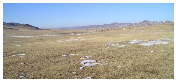 |
| Figure 14 Investigation site for the proposed international freight and logistics Ulaanbaatar terminal |
Due to seasonal precipitation, temporary water flows from south to north, accumulating in the eastern area streaming along the mountain valley. A formation of swamp hammocks has arisen in the eastern area of the site, under the influence of surface water evaporation and infiltration.
Upon completion of the borehole drilling up to a depth of 20.0 m, scattered permafrost was encountered from 3.5 and 4.0 m up to end of the borehole. Distribution of permafrost soil was continued until the target depth. Encountered permafrost is classified as hard frozen ground connected with a seasonal freeze-thawing depth. Permafrost temperature varies between −0.2 °С and −0.3 °С under depths of 4.0 and 20.0 m(Batsaikhan and Rentsendorj, 2012).
Insertion of ice wedges extend to a depth of 8.0 m and below 8.0 m the ice segregates. Formation of discrete layer or lenses of segregated ice varies between 5 and 15 cm. There are numerous small hummocks and some huge pingos have been formed in poorly drained areas. Surface water stream yielded stream beds with depths of 50-60 cm.
4.2 Soil characteristicThe Ulaanbaatar terminal site is comprised of poorly graded gravel including clayey sand . Due to evaporation and infiltration, the clayey soils are slight to medium heaving soils in seasonal freezing depth. A geological section of the soil is present in Figure 15, and determination of physical and mechanical properties of soils in frozen and defrosted conditions is provided in Tables 8 and 9.
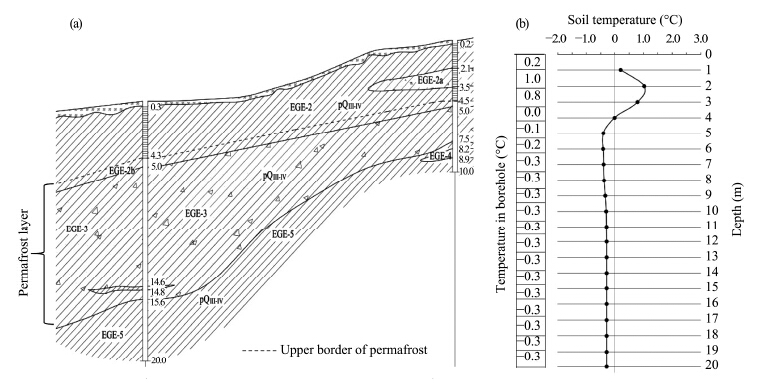 |
| Figure 15 Geological section(a) and borehole temperature measurements(b)for Ulaanbaater terminal site |
| Soil characteristics | EGE-3 clayey gravel with silt | EGE-4 clayey gravel with s and |
| Gravel(%) | 40.5 | 61.7 |
| S and (%) | 30.2 | 19.9 |
| Silt(%) | 16.9 | 7.5 |
| Clay(%) | 12.4 | 5.5 |
| Natural moisture content, W(%) | 0.091 | 0.075 |
| Degree of saturation, Sr(%) | 0.61 | 0.68 |
| Consistency, JL | <0 | <0 |
| Liquid limit, WL(%) | 0.256 | 0.214 |
| Plastic limit, Wp(%) | 0.165 | 0.134 |
| Plasticity index, Jp | 0.091 | 0.080 |
| Density, γs(g/cm3) | 2.72 | 2.72 |
| Specific gravity, γo(g/cm3) | 2.11 | 2.26 |
| Dry density, γ(g/cm3) | 1.94 | 2.10 |
| Porosity, n(%) | 28.92 | 22.67 |
| Voids ratio, e | 0.410 | 0.290 |
| Soil characteristics | EGE-3 Clayey gravel with silt | EGE-4 Clayey gravel with s and | |||
| Normative | Calculation | Normative | Calculation | ||
| Cohesion, C(kPа) | 47 | 31.3 | 21 | 14.0 | |
| Angle of internal friction, φ(°) | 25 | 21.7 | 42 | 36.5 | |
| Module of deformation(MPa) | 33 | 44 | |||
| Design strength(kPа) | 300 | 450 | |||
Development of the Urgakh Naran residential complex is viewed as the solution to the increasing population concentration in Ulaanbaatar(Figure 16). "Urgakh Naran" means "rising sun" since the planned construction will be located southwest of Ulaanbaatar City. Specifically, the site is located between Nalaikh District and Ulaanbaatar, in territory of 11th khoroo of Bayanzurkh district of the capital, 3 km southeast from the Bayan-Zurkh regional station, and 200 m east from the existing road between Ulaanbaatar and Nalaikh.
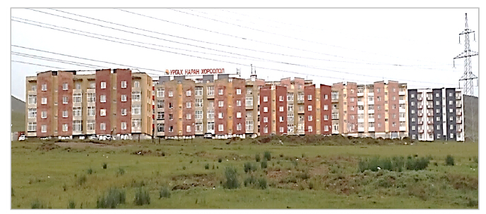 |
| Figure 16 View of Urgakh Naran residential complex |
The ground surface is slightly sloped and has characteristics of sedimentary relief accumulated in lower areas. The site ground elevation varies between 1, 380.6 and 1, 384.7 m with relative differences of 4.1 m. Surface washout is medium active. Surface erosion and denudation processes are actively developed along both sides.
Top soil depth ranges from 0.20 to 0.30 m, dominated by poorly graded s and with gravel and silt, including vegetation roots, with a yellowish brown color. The top soil overlies the Upper and Modern Quaternary aged(dpQIII-IV)dilivium-proluvium deposits of predominately silty, clayey s and soil, of a light yellowish to reddish yellow color which extends to a depth of 15.0 m(end of drilling core). Based on summarized data from the boreholes, it was found that the site contains four different engineering geological elements(EGEs). Figure 17 shows that the permafrost upper boundary starts from 7.0 m and reaches up to 10 m below the ground surface(Batsaikhan and Rentsendorj, 2011).
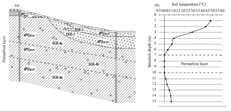 |
| Figure 17 Geological section(a) and temperature measurements(b)for Urgakh Naran residential complex site |
Physical and thermophysical properties of soils are described in Tables 10, 11 and 12.
| Physical properties | EGE-1 Silty clayey s and | EGE-2 Poorly graded gravel with s and and silt | EGE-3 Clayey gravel with s and | EGE-4 Clayey gravel with s and |
| Pebble(%) | 3.5 | 34.6 | 21.7 | 26.4 |
| Gravel(%) | 7.8 | 25.3 | 35.7 | 18.1 |
| S and (%) | 49.6 | 21.8 | 28.0 | 31.2 |
| Silt(%) | 22.7 | 10.6 | 8.3 | 14.0 |
| Clay(%) | 16.4 | 7.7 | 6.3 | 10.3 |
| Natural moisture content, W(%) | 0.074 | 0.060 | 0.069 | 0.085 |
| Degree of saturation, Sr(%) | 0.30 | 0.53 | 0.59 | 0.67 |
| Specific gravity, γo(g/cm3) | 2.72 | 2.70 | 2.72 | 2.72 |
| Density, γd(g/cm3) | 1.76 | 2.20 | 2.21 | 2.13 |
| Dry density, γd(g/cm3) | 1.63 | 2.08 | 2.06 | 1.96 |
| Porosity, n(%) | 39.92 | 22.94 | 24.13 | 27.83 |
| Voids ratio, e | 0.665 | 0.298 | 0.318 | 0.36 |
| Plasticity index, Jp | 0.076 | 0.060 | 0.076 | 0.063 |
| Physical properties | EGE-3 Clayey gravel with silt(dpQIII-IV) |
| Total moisture content of frozen soil, Wtot(%) | 0.137 |
| Water-absorbing capacity/hygroscopic moisture content, Ww(%) | 0.095 |
| Water content interface between the ice, Wm(%) | 0.136 |
| Ice water content in the pore spaces between the solid soil particles, Wic(%) | 0.041 |
| Water content in unfrozen soil, Wi(%) | 0.002 |
| Liquid limit, Wl(%) | 0.239 |
| Plastic limit, Wp(%) | 0.136 |
| Plasticity index, Jp | 0.101 |
| Specific gravity in frozen condition, γs(g/cm3) | 2.73 |
| Specific gravity, γo(g/cm3) | 1.95 |
| Dry density, γd(g/cm3) | 1.80 |
| Voids ratio, e | 0.513 |
| Degree of saturation in the pores, Sr(%) | 1.297 |
| Total ice content, itot(%) | 0.110 |
| Ice content, iic(%) | 0.089 |
| Soil thawing settlement-A | Relative subsidence under pressure, a | Compressibility coefficient under pressure | Thermophysical characteristics | ||||||||
| 1.0(kg/sm2) | 3.0(kg/sm2) | 1.0(kg/sm2) | 3.0(kg/sm2) | Coefficient of thermal conductivity(kCal/(m∙h∙°C)) | Volumetric heat capacity(kCal/(m3∙°C)) | ||||||
| λf | λth | Cf | Cth | ||||||||
| 0.003 | 0.078 | 0.089 | 0.038 | 0.054 | 1.35 | 1.55 | 660 | 540 | |||
According to permafrost distribution mapping of Mongolia, the Urgakh Naran site is situated within the Khentii mountainous range of sporadic and scattered permafrost. The site can be defined to have an epigenetic origin with an average thickness of about 3.0 m, and a maximum thickest of 7.0-10.0 m.
5.2 The thermal regime of foundation base on permafrostFrost heaving or thawing can lead to a serious loss of stability and cause damage to structures. Thus, an estimated thermal regime is required for the construction of foundations on permafrost soils. Consideration of instability of frozen soil and its possible negative changes due to temperature fluctuations is important in order to avoid structural damage. For instance, as frozen soil temperatures increase, soil bearing strength decreases causing soil collapse and settlement. Therefore, calculation of heat transfer from building to soil is highly recommended to prevent structural damage.
The heat transfer takes a form of a curve(Figure 18). With heat transfer, the soil becomes instable at first but later gradually stabilizes. At the foundation core, the heat flows downward to the center without transfer to lateral sides. Therefore, heat transfer has a linear form and can be estimated by linear steady-state equation of Fourier(Tsytovich, 1972). The amount of heat transferred to the soil Q has a direct relationship with the difference between the temperatures of two environments that the heat passes through, and an inverse relationship with heat transfer resistance of the foundation R0.
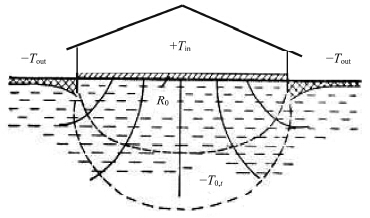 |
| Figure 18 Heat transfer from building to permafrost |
| $Q = \frac{{{T_{in}} - {T_0}}}{{{R_0}}} \cdot t$ | (1) |
In other words, the higher the temperature inside the structure the greater the loss of temperature gradient. The maximum temperature of permafrost below the top soil can be estimated using following equation:
| ${T_{\max }} = {\alpha _t}{k_t}{T_0}$ | (2) |
The permafrost temperature is determined at three different points of construction. First, at the center of the building base as follows:
| ${T_{m,z,e}} = \left( {{{T'}_0} - {T_{bf}}} \right){\alpha _{m,z,c}} + \left( {{T_0} - {{T'}_0}} \right){K_1} + {T_{bf}}$ | (3) |
| ${T_{m,z,e}} = \left( {{{T'}_0} - {T_{bf}}} \right){\alpha _{m,z,c}} + \left( {{T_0} - {{T'}_0}} \right)\left( {0.5{\alpha _{m,z,c}} + {K_2}} \right) + {T_{bf}}$ | (4) |
| ${T_{m,z,e}} = {\rm{ }}\left( {{{T'}_0} - {T_{bf}}} \right){\alpha _{m,z,c}} + \left( {{T_0} - {{T'}_0}} \right)\left( {0.7{\alpha _{m,z,c}} + {K_3}} \right) + {T_{bf}}$ | (5) |
There are two principles of foundation design in constructing buildings on permafrost. The first is keeping the soil permanently frozen; and the second is thawing and compacting permafrost before the construction or taken into account thawing process and construct directly on permafrost. The lower the average annual air temperature the higher the possibility of permafrost in the area. The most appropriate method in areas with continuous permafrost is to keep the permafrost in a frozen state. If permafrost is not detected despite low air temperature, the foundation design should take seasonal freezing into account(Dashjamts et al., 2009). The following methods used to keep permafrost in a permanently frozen condition according to the first principle are illustrated in Figure 19.
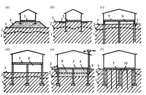 |
| Figure 19 Methods of keeping permafrost in a frozen state. 1- permafrost; 2- the upper limit of frozen soil; 3- the maximum depth in seasonal freezing cycle; 4- non frost heave backfill as a base; 5- thermal isolation; 6- insulation and ventilation; 7- pile foundation; 8- natural insulation system; 9- mechanic coolant system; 10- ammonia filled cooling pipes |
I: Constructing foundation on the compacted backfill or damp soil;
II: Covering foundation with thermal insulation material to prevent heat transfer to the soil;
III: Raising the building above the surface by shallow and pile foundation;
IV: Construction above the surface compartments without heating to avoid heat transfer from the building;
V: Constructing air duct foundation;
VI: Installing additional cooling system under the structure.
Keeping permafrost in a frozen state is a common method of construction in Mongolia. It is proven from many years' construction experience that the best way to keep permafrost in climatic and geocryological conditions of Mongolia is installing ventilation hollows under the building. Estimation of mezo and micro factors of the area and dimension of the entire building with its thermo-technical indicators is perquisite to keeping permafrost in a frozen condition by constructing ventilation hollows. The appropriate size of the ventilation hollow and the temperature inside it should be estimated for each case individually. Research results conducted on permafrost of Mongolia, thermal regime of building bases and soil temperature measurements indicate that the main factor affecting stability of foundation constructed on permafrost is climatic conditions of the area. Therefore, estimation of appropriate temperatures in ventilation hollows has become a major issue to be solved. This estimation would help solve the problems of foundation design on permafrost. The basic requirement for maintaining soil in a frozen condition is keeping ventilation hollows constantly cool.
Constant cooling of ventilation hollows stabilizes the temperature of the buildings frozen base. In other words, cooling devices helps reduce the temperature of the active soil layer that was heated from the structure, and keeps the temperature of the permafrost deposit under this layer constant. The difference between the temperature of upper boundary of permafrost deposit(or bottom of the active soil layer) and temperature in ventilation hollow is related to the difference between thermal conductivity coefficients of frozen and thawed soil.
The temperature of upper boundary of permafrost layer should be below or equal to the temperature inside the ventilation hollow(estimation made for summer time):
| ${{{T'}_0}} \le {T_{c,a}}$ | (6) |
| ${\rm{ }}{{{T'}_0}} = {\rm{ }}{T_{c,a}} - \left( {1 - {\lambda _{th}}/{\lambda _f}} \right){\rm{ }}{T_{th,ca}}\frac{{{\tau _{th}}}}{{{\tau _y}}}$ | (7) |
| ${T_{c, a}} = {k_0} \cdot {T_0}$ | (8) |
| ${k_0} = 1/\left[ {1 - \frac{{{\tau _{th}} - \frac{{{\tau _y}}}{{{\rm{\pi tg}}({\rm{\pi }}{t_{th}}/{\tau _y})}}}}{{{\tau _y}}} \cdot (1 - \frac{{{\lambda _{th}}}}{{{\lambda _f}}})} \right]$ | (9) |
Upon determination of geocryological conditions, the Urgakh Naran residential complex foundation was designed following the aforementioned construction methodology. The time required for complete melting of permafrost at 7 m depth from the surface was estimated. On the other hand , possible solutions were carefully considered in case the permafrost was kept in a frozen state. Possible solutions included insulation of the basement floor with polystyrene foam, and in stallment of air ducts in the foundation. Figure 20 presents the case where the basement floor was insulated with 200 mm thick polystyrene foam. The amount of settlement due to thawing was estimated for 0, 1, 2, 5, 10, and 50 years of building exploitation period when the internal temperature in basement floor Tin does not exceeding +2 °С.
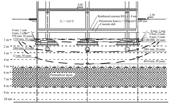 |
| Figure 20 Foundation design and heat distribution scheme of thawing soil for period of 1, 5, 10, 20 and 50 years(version 1) |
For the second solution(Figure 21), in addition to insulation, the foundation was designed to have air ducts in order to provide air circulation with cooling effect. It was estimated that the structural stability can be maintained for 50 years keeping the permafrost in a frozen condition, even if the internal temperature is much warmer around +10 °С. Therefore, the second case with insulation and installation of air ducts was considered as optimal for foundation design for the Urgakh Naran apartment complex.
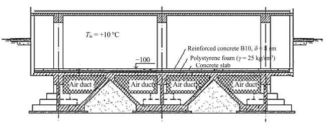 |
| Figure 21 Foundation design(version 2) |
In this second foundation design, the module of air ventilation is defined as follows:
| $M = {A_v}/{A_b}$ | (10) |
This paper presents findings from geotechnical investigationsconducted in Nalaikh Depression located above continous, sporadic and scattered permafrost. Findings from three different construction sites were presented: university campus, Ulaanbaatar terminal, and Urgakh naran residential complex.
1)Findings from university campus geotechnical investigation.
 The proposed university campus consists of continuous permafrost spreading distribution to 22.0 m(the end of drilling). A water-filled depression exists in the upper and mid layers of permafrost under the permafrost pingo with a height of 3.0 m and diameter of 50-60 m. Annual average temperature varies between 0 °C and −0.2 °C. Based on these arguments, the proposed construction site is located within complicated geotechnical condition.
 The site consists of massive to ataxite textured clayey deposition. Temperatures under 10-15 m from the ground surface varies between −0.23 °C to −0.15 °C. Permafrost upper boundary starts from 2.9-3.1 m. The seasonal freezing and thawing depth varies at these depths.
2)Findings from Ulaanbaatar terminal geotechnical investigation.
 If the construction foundation footing is based on permafrost soil, the permanently frozen soil should be kept in a frozen condition following the principle of thaw prevention.
 Top soil should be completely removed and backfilled with non-heaving soils. It is noted that proper calculation, design and plan on foundations(construction building and facility)are required to prevent frost heave and thermal infiltration.
3)Findings from Urgakh Naran apartment complex site.
This site is the most challenging for foundation design as permafrost layer is s and wiched between soil layers. Foundation design in such case was developed to keep permafrost in a frozen state by applying insulation material along with installation of air ducts. Main findings from these three sites can be concluded as follows:
 The site comprised scattered permafrost with permafrost thickness reaching up to 5 m. Keeping the permafrost soil in frozen state is considered as an optimal option for foundation design.
 Permafrost layer varies in thickness and lies between 7 and 10 m depth below the construction footing, with a thickness of 3.0-5.0 m. The proper structural design requires that the basement indoor temperature remain at +5 °C through the air duct system and by insulating the basement floor.
1)Building length: L=44.5 m
2)Building width: B=15.2 m
3)Reinforced concrete panel: б=0.16 m
4)Thermal foam or insulation panel: б1=100 mm, б2=200 mm(Density ρ=150 kg/m3, R0=2.331 °C/kCal)
5)Indoor basement temperature: Ti=+5 °C
6)Basement floor thermal resistance: R0=2.142((m2·°C)/W)=2.496((m2·°C)/kCal)
| No. | Design structure of the footing | Thickness, L(m) | Thermal conductivity, λ(W/(m2·°C)) | Thermal resistance, R0=hi/λ((m2·°C)/W) |
| 1 | Concrete | 0.08 | 1.69 | 0.0473 |
| 2 | Insulating polystyrene foam | 0.10 | 0.05 | 2.0000 |
| 3 | Basement reinforced concrete slab | 0.16 | 1.69 | 0.0946 |
| Total | 2.1420 | |||
1)Density of frozen soil: γ1=2.13 t/m3
2)Dry density of frozen soil: γ2=1.96 t/m3
3)Total moisture: Wtot =8.5%
4)Moisture content between ice lenses: Wm =0.04%
5)Soil temperature at depth of 10 m: T0 = −0.3 °C
6)Seasonal thawing depth: dth.n =2.6 m
7)Relative thaw subsidence: A=0.003
8)Thaw compaction ratio: a=0.038 sm3/kg
9)Plastic index: Jp=0.02
10)Unfrozen water content: 5%
11)Freeze-up temperature: Wbf =−0.23 °C
3 Comment:1)Permafrost upper limit:5.2 m
2)Permafrost lower limit: 8.2 m
3)Footing depth: 1.8 m
4)Freeze-thaw layer depth above the frozen soil: 5.2−1.8=3.4 m
4 Construction foundation definition:1)Width and length of the main base column: B=4.5 m, L=4 m
2)Width and length of the boundary column: B=4.5 m, L=4 m
3)Load pressure on the main base column: N1=8, 100 kN=810 t
4)Load pressure on boundary column: N2=6, 992 kN=699.2 t
5)Average pressure on the main base column: Pm1=400 kPa=40, 000 kg/m2=4 kg/cm2
6)Average pressure on boundary column: Pm2=395.04 kPa=34, 528.4 kg/m2=3.453 kg/sm2
| Thawing period(year) | Thermal conductance depth of thermo-isolated basement floor with thickness of 100 mm(m) | Expected additional settlement(sm) | ||||
| Main base | Boundary column | Main base | Boundary column | |||
| 5 | 3.611 | 1.182 | -- | -- | ||
| 10 | 5.66 | 2.204 | 7.046 | -- | ||
| 20 | 7.814 | 3.496 | 37.572 | -- | ||
| 50 | 10.348 | 6.509 | 42.615 | 17.032 | ||
| Total subsidence | 42.615 | 17.032 | ||||
| Thawing period(year) | Thermal conductance depth of thermo-isolated basement floor with thickness of 200 mm(m) | Expected additional settlement(sm) | ||||
| Main base | Boundary column | Main base | Boundary column | |||
| 5 | 0.602 | 0.000 | -- | -- | ||
| 10 | 1.341 | 1.311 | -- | -- | ||
| 20 | 2.802 | 2.464 | -- | -- | ||
| 50 | 4.615 | 3.713 | -- | -- | ||
| Total subsidence | -- | -- | ||||
| It is noted that the soil will keep its frozen state for 50 years. | ||||||
 2015, 7


